Keeping up with the times, it was decided to continue the theme of controlling tube power amplifiers. The use of a color 3.2-inch graphic display, as well as a powerful 32-bit microcontroller on the ARM Cortex-M3 core allows expanding the capabilities of the new control board. 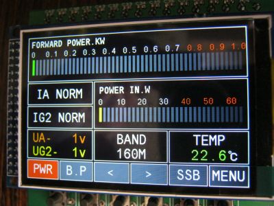
The capabilities of the control and monitoring unit of the modern PA-CONTROL VER.4 power amplifier are as follows: 1. Switching the PA on/off by a timer with a certain sequence of applying voltage to the lamp electrodes.
2. Protection by anode and screen grid current.
3. Indication of screen and anode voltage.
4. Indication of output and input power.
5. Measuring the air flow temperature.
6. Blocking the transmission in case of exceeding the set air flow temperature.
7. Switching between 9 sub-ranges with the "<" and ">" buttons (160M, 80M, 40M, 30M, 20M, 17M, 15M, 12M, 10M).
8. "SSB/CW" modes.
9. "BP" bypass mode
10. Switching the PA off by a timer or by a set air flow temperature value. All parameters are configured in the menu and saved in non-volatile memory. Electrical schematic diagram. 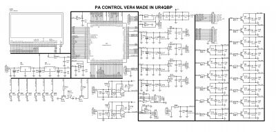
The heart of the control board is a 32-bit STM32F103VCT6 microcontroller on the ARM Cortex-M3 core with a flash memory of 256 KB and RAM of 48 KB. The microcontroller operates at a frequency of 72 MHz. The 3.2" display with a resolution of 320x480 pixels operates on a 16-bit bus through the STM32F103VCT6 FSMC controller. The display has a driver on the controller from ILITEK ILI9481. The display backlight is controlled via transistor Q17. Since the backlight is always connected in this display, it had to be modified again with a "file". I also had to remove the SD card slot because it interfered with the trimmer resistors on the board. 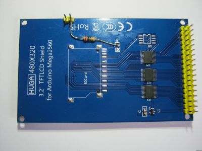
To save the control board settings, I did not use the microcontroller's flash, but used an external 2 kbit M24C02 EEPROM that exchanges data with the microcontroller via the I2C bus. This decision was made due to the limited number of flash memory write/erase cycles, and STM32 microcontrollers do not have an internal EEPROM. The anode and screen grid voltages, as well as the forward wave of the output and input power, are measured by a 12-bit microcontroller ADC operating in cyclic mode via a DMA controller. The ADC inputs are protected by 3.3 V zener diodes. High-voltage dividers for measuring the anode and screen voltage should provide a ratio of 1:1000, i.e. up to 30 V at the input. The exact readings are adjusted by trimmer resistors on the board. For example, fragments of rectifier circuits with voltmeter dividers of my RA.  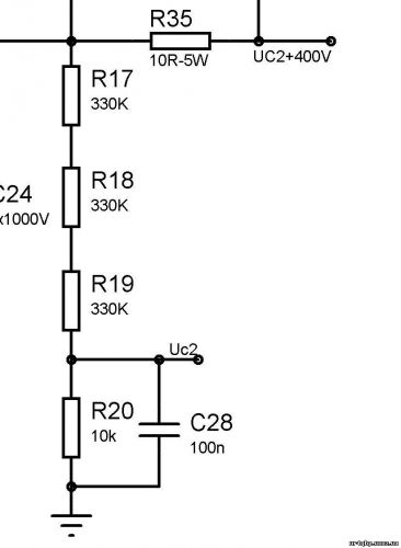
The keys for controlling the amplifier relay are made on bipolar pnp transistors BD139 with an open collector and protection by 1N4148 diodes. The pedal is connected to the J15 terminal block, protected from extraneous voltage by a 3.3 V zener diode. It is switched to the transmission mode by closing J15 "PTT_KEY". The protections for the anode and second grid currents are implemented in a similar way to the third version of the control board. Optocouplers are used for galvanic isolation from high-voltage circuits. According to the screen grid current, they are connected in opposite parallel, since the screen grid current can be both positive and negative. According to the anode current, one optocoupler is connected in parallel to the shunt in the "minus" of the anode rectifier. The shunt must be calculated in such a way as to ensure that the optocoupler opens at a current close to the desired protection response current. As a rule, 10 ... 20 Ohm for the screen voltage and 1 Ohm for the anode. Optocouplers 4N35, similar ones are possible. 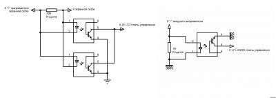
The anode protection optocoupler is connected to terminal block J9, and the screen grid protection to J10. The protection response threshold is set by trimmer multi-turn resistors R21 and R25, respectively. The outputs of protection comparators U6 and U5 are connected to the GPIO of the microcontroller and configured for an input with an external interrupt. That is, no matter what the microcontroller is "busy" with, the protection will work first.  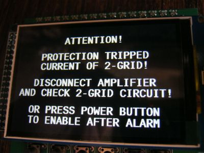
When the protection is triggered, the voltage of the anode and the second grid is removed, the amplifier starts up after the protection is triggered without the "starting" heating of the lamp. The turn-on time after the protection is triggered is set in the menu (further in the text). 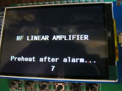
The buzzer (speaker) for the sound accompaniment of the control unit is connected via transistor Q17 and works with the DAC of the microcontroller via DMA. A digital temperature sensor for measuring the air flow of cooling the DS18B20 lamp is connected to terminal block J14 via the "1-Wire" bus. The maximum value of the measured temperature is 130 degrees Celsius (125 according to the datasheet). The display constantly shows the flow temperature value and there are protections using this sensor. Blocking the inclusion of the transmission mode when the temperature limit is exceeded, as well as changing the display color at a temperature close to the maximum. It is also possible to turn off the PA when a certain temperature is reached when "blowing" the lamp before turning it off. The parameters and operating mode are configured in the menu. The board has 6 control buttons, they are installed below the display and their purpose is shown on the display. "PWR" - on/off, "BP" - bypass mode (in this mode, the board is blocked from turning on for transmission), "<" - range down, ">" - range up, "SSB" - SSB or CW operating modes (the inscription changes depending on the mode) and "MENU" - menu entry button. 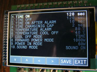
The settings menu is intuitive, all navigation buttons have labels. "^" and "v" - select a menu item, "<" and ">" - select the value of this menu item. 1. "TIME ON" - timer on time from 10 to 300 seconds in 10 second increments. 2. "TIME OFF" - timer off (purge) from 10 to 300 seconds in 10 second increments. 3. "TIME ON AFTER ALARM" - timer for switching on after an accident from 5 to 30 seconds in 1 second increments. 4. "TIME CHARGINIG CAP" - the timer for charging the anode rectifier capacitor from 1 to 5 seconds in 1 second increments. 5. "TEMPERATURE ALARM" - air flow temperature of transmission mode blocking from 50 to 130 degrees Celsius in 5 degree increments. 6. "TEMPERATURE COOL OFF" - air flow temperature in cooling mode before switching off the amplifier from 30 to 85 degrees Celsius in 5 degree increments. 7. "COOL OFF MODE" - amplifier shutdown mode: by timer time - "TIME" (menu item 2) or by air flow temperature - "TEMP" (menu item 6). 8. "FORWARD POWER MODE" - maximum output power display value: 500, 750, 1000, 1500 and 2000 W. 9. "POWER IN MODE - maximum value of input power display: 30, 60 and 120 W. 10. "SOUND MODE" - turn on/off sound, "ON" or "OFF" respectively. To save the settings, you need to press the "SAVE" button, and "OK" will be heard in Morse code to confirm that the settings have been saved. The board is powered from a non-stabilized source with a voltage of 8-15 V, stabilized is also possible. The current consumption of the board in the on mode is about 100 mA. I recommend that all board settings be performed without supplying high voltages to the PA. Structurally, the control unit is made on a double-sided printed circuit board measuring 91 x 75 mm. All connections to the board are made using terminal blocks with screw clamps, i.e. there is no need to solder anything here.   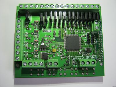
Mounting diagram with terminal block pinout, view from the terminal block side. 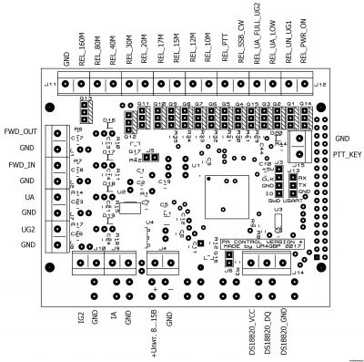
Layout of trimmer resistors for setting protection comparators and measuring input/output power voltages. View from the display installation side. 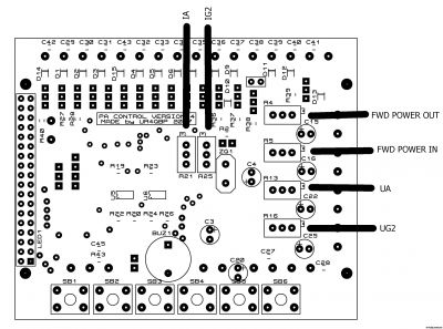
Good luck to everyone, successful PA and worthy antennas! Best regards, Alexander UR4QBP
|